The Boiler House

Contents
Boiler Efficiency and Combustion
A broad overview of the combustion process, including burner types and controls, and heat output and losses.
This Module is intended to give a very broad overview of the combustion process, which is an essential component of overall boiler efficiency. Readers requiring a more in-depth knowledge are directed towards specialist textbooks and burner manufacturers.
Boiler efficiency simply relates energy output to energy input, usually in percentage terms:
‘Heat exported in steam’ and ‘Heat provided by the fuel’ is covered more fully in the following two Sections.
Heat exported in steam - this is calculated (using the steam tables) from knowledge of:
Heat provided by the fuel
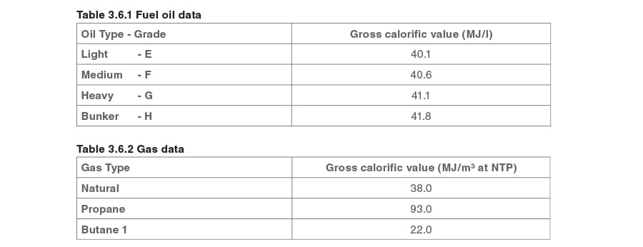
Calorific value
This value may be expressed in two ways ‘Gross’ or ‘Net’ calorific value.
Gross calorific value
This is the theoretical total of the energy in the fuel. However, all common fuels contain hydrogen, which burns with oxygen to form water, which passes up the stack as steam.
The gross calorific value of the fuel includes the energy used in evaporating this water. Flue gases on steam boiler plant are not condensed, therefore the actual amount of heat available to the boiler plant is reduced.
Accurate control of the amount of air is essential to boiler efficiency:
- Too much air will cool the furnace, and carry away useful heat.
- Too little air and combustion will be incomplete, unburned fuel will be carried over and smokemay be produced.
Net calorific value
This is the calorific value of the fuel, excluding the energy in the steam discharged to the stack,and is the figure generally used to calculate boiler efficiencies. In broad terms:
Accurate control of the amount of air is essential to boiler efficiency:
- Too much air will cool the furnace, and carry away useful heat.
- Too little air and combustion will be incomplete, unburned fuel will be carried over and smoke may be produced.
In practice, however, there are a number of difficulties in achieving perfect (stoichiometric) combustion:
- The conditions around the burner will not be perfect, and it is impossible to ensure the complete matching of carbon, hydrogen, and oxygen molecules.
- Some of the oxygen molecules will combine with nitrogen molecules to form nitrogen oxides (NOx).
To ensure complete combustion, an amount of ‘excess air’ needs to be provided. This has an effect on boiler efficiency.
The control of the air/fuel mixture ratio on many existing smaller boiler plants is ‘open loop’. That is, the burner will have a series of cams and levers that have been calibrated to provide specific amounts of air for a particular rate of firing.
Clearly, being mechanical items, these will wear and sometimes require calibration. They must, therefore, be regularly serviced and calibrated.
On larger plants, ‘closed loop’ systems may be fitted which use oxygen sensors in the flue to control combustion air dampers.
Air leaks in the boiler combustion chamber will have an adverse effect on the accurate control of combustion.
Legislation
Presently, there is a global commitment to a Climate Change Programme, and 160 countries have signed the Kyoto Agreement of 1997. These countries agreed to take positive and individual actions to:
- Reduce the emission of harmful gases to the atmosphere -
Although carbon dioxide (CO2) is the least potent of the gases covered by the agreement, it is by far the most common, and accounts for approximately 80% of the total gas emissions to be reduced.
- Make quantifiable annual reductions in fuel used -
This may take the form of using either alternative, non-polluting energy sources, or using the same fuels more efficiently.
In the UK, the commitment is referred to as ‘The UK National Air Quality Strategy’, and this is having an effect via a number of laws and regulations. Other countries will have similar strategies.
Technology
Pressure from legislation regarding pollution, and from boiler users regarding economy, plus the power of the microchip have considerably advanced the design of both boiler combustion chambers and burners.
Modern boilers with the latest burners may have:
- Re-circulated flue gases to ensure optimum combustion, with minimum excess air.
- Sophisticated electronic control systems that monitor all the components of the flue gas, and make adjustments to fuel and air flows to maintain conditions within specified parameters.
- Greatly improved turndown ratios (the ratio between maximum and minimum firing rates) which enable efficiency and emission parameters to be satisfied over a greater range of operation.
Heat losses
Having discussed combustion in the boiler furnace, and particularly the importance of correct air ratios as they relate to complete and efficient combustion, it remains to review other potential sources of heat loss and inefficiency.
Heat losses in the flue gases
This is probably the biggest single source of heat loss, and the Engineering Manager can reduce much of the loss.
The losses are attributable to the temperature of the gases leaving the furnace. Clearly, the hotter the gases in the stack, the less efficient the boiler.
The gases may be too hot for one of two reasons:
- The burner is producing more heat than is required for a specific load on the boiler:
This means that the burner(s) and damper mechanisms require maintenance and re-calibration. - The heat transfer surfaces within the boiler are not functioning correctly, and the heat is not being transferred to the water:
This means that the heat transfer surfaces are contaminated, and require cleaning.
Some care is needed here - Too much cooling of the flue gases may result in temperatures falling below the ‘dew point’ and the potential for corrosion is increased by the formation of:
Nitric acid (from the nitrogen in the air used for combustion).
Sulphuric acid (if the fuel has a sulphur content).
Water.
Radiation losses
Because the boiler is hotter than its environment, some heat will be transferred to the surroundings.
Damaged or poorly installed insulation will greatly increase the potential heat losses.
A reasonably well-insulated shell or water-tube boiler of 5 MW or more will lose between 0.3 and 0.5% of its energy to the surroundings.
This may not appear to be a large amount, but it must be remembered that this is 0.3 to 0.5% of the boiler’s full-load rating, and this loss will remain constant, even if the boiler is not exporting steam to the plant, and is simply on stand-by.
This indicates that to operate more efficiently, a boiler plant should be operated towards its maximum capacity. This, in turn, may require close co-operation between the boiler house personnel and the production departments.
Burners and controls - Burners are the devices responsible for:
Burner turndown
An important function of burners is turndown. This is usually expressed as a ratio and is based on the maximum firing rate divided by the minimum controllable firing rate.
The turndown rate is not simply a matter of forcing differing amounts of fuel into a boiler, it is increasingly important from an economic and legislative perspective that the burner provides efficient and proper combustion, and satisfies increasingly stringent emission regulations over its entire operating range.
As has already been mentioned, coal as a boiler fuel tends to be restricted to specialised applications such as water-tube boilers in power stations.
Oil burners
The ability to burn fuel oil efficiently requires a high fuel surface area-to-volume ratio. Experience has shown that oil particles in the range 20 and 40 μm are the most successful.
Particles which are:
- Bigger than 40 μm tend to be carried through the flame without completing the combustion process.
- Smaller than 20 μm may travel so fast that they are carried through the flame without burning at all.
A very important aspect of oil firing is viscosity. The viscosity of oil varies with temperature: the hotter the oil, the more easily it flows. Indeed, most people are aware that heavy fuel oils need to be heated in order to flow freely. What is not so obvious is that a variation in temperature, and hence viscosity, will have an effect on the size of the oil particle produced at the burner nozzle.
For this reason the temperature needs to be accurately controlled to give consistent conditions at the nozzle.
Pressure jet burners
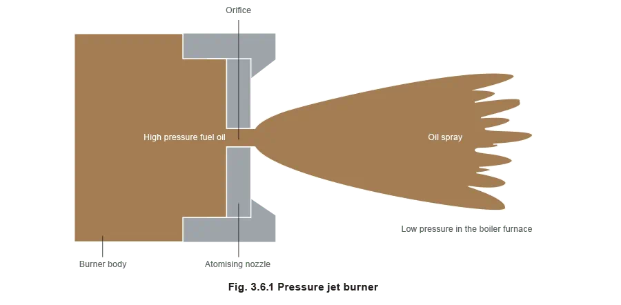
A pressure jet burner is simply an orifice at the end of a pressurised tube. Typically the fuel oil pressure is in the range 7 to 15 bar.
In the operating range, the substantial pressure drop created over the orifice when the fuel is discharged into the furnace results in atomisation of the fuel. Putting a thumb over the end of a garden hosepipe creates the same effect.
Varying the pressure of the fuel oil immediately before the orifice (nozzle) controls the flowrate of fuel from the burner.
If the fuel flowrate is reduced to 50%, the energy for atomisation is reduced to 25%.
This means that the turndown available is limited to approximately 2:1 for a particular nozzle. To overcome this limitation, pressure jet burners are supplied with a range of interchangeable nozzles to accommodate different boiler loads.
Advantages of pressure jet burners:
- Relatively low cost.
- Simple to maintain.
Disadvantages of pressure jet burners:
- If the plant operating characteristics vary considerably over the course of a day, then the boiler will have to be taken off-line to change the nozzle.
- Easily blocked by debris. This means that well maintained, fine mesh strainers are essential.
Rotary cup burner
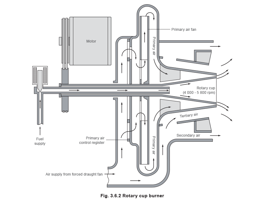
Fuel oil is supplied down a central tube, and discharges onto the inside surface of a rapidly rotating cone. As the fuel oil moves along the cup (due to the absence of a centripetal force) the oil film becomes progressively thinner as the circumference of the cap increases. Eventually, the fuel oil is discharged from the lip of the cone as a fine spray.
Because the atomisation is produced by the rotating cup, rather than by some function of the fuel oil (e.g. pressure), the turndown ratio is much greater than the pressure jet burner.
Advantages of rotary cup burners:
- Robust.
- Good turndown ratio.
- Fuel viscosity is less critical.
Disadvantages of rotary cup burners:
- More expensive to buy and maintain.
Gas burners
At present, gas is probably the most common fuel used in the UK.
Being a gas, atomisation is not an issue, and proper mixing of gas with the appropriate amount of air is all that is required for combustion.
Two types of gas burner are in use ‘Low pressure’ and ‘High pressure’.
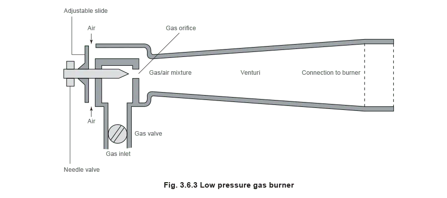
Low pressure burner
These operate at low pressure, usually between 2.5 and 10 mbar. The burner is a simple venturi device with gas introduced in the throat area, and combustion air being drawn in from around the outside.
Output is limited to approximately 1 MW.
High pressure burner
These operate at higher pressures, usually between 12 and 175 mbar, and may include a number of nozzles to produce a particular flame shape.
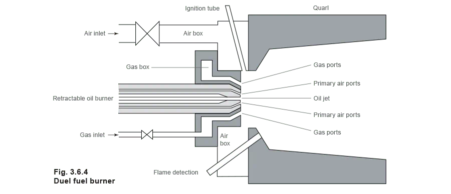
Dual fuel burners
The attractive ‘interruptible’ gas tariff means that it is the choice of the vast majority of organisationsin the UK. However, many of these organisations need to continue operation if the gas supply is interrupted.
The usual arrangement is to have a fuel oil supply available on site, and to use this to fire the boiler when gas is not available. This led to the development of ‘dual fuel’ burners.
These burners are designed with gas as the main fuel, but have an additional facility for burning fuel oil.
The notice given by the Gas Company that supply is to be interrupted may be short, so the change over to fuel oil firing is made as rapidly as possible, the usual procedure being:
- Isolate the gas supply line.
- Open the oil supply line and switch on the fuel pump.
- On the burner control panel, select ‘oil firing’. (This will change the air settings for the different fuel).
- Purge and re-fire the boiler.
This operation can be carried out in quite a short period. In some organisations the change over may be carried out as part of a periodic drill to ensure that operators are familiar with the procedure, and any necessary equipment is available.
However, because fuel oil is only ‘stand-by’, and probably only used for short periods, the oil firing facility may be basic.
On more sophisticated plants, with highly rated boiler plant, the gas burner(s) may be withdrawn and oil burners substituted.
Burner control systems
The reader should be aware that the burner control system cannot be viewed in isolation. The burner, the burner control system, and the level control system should be compatible and work in a complementary manner to satisfy the steam demands of the plant in an efficient manner.
The next few paragraphs broadly outline the basic burner control systems.
On/off control system
This is the simplest control system, and it means that either the burner is firing at full rate, or it is off. The major disadvantage to this method of control is that the boiler is subjected to large and often frequent thermal shocks every time the boiler fires. Its use should therefore be limited to small boilers up to 500 kg/h.
Advantages of an on/off control system:
- Simple.
- Least expensive.
Disadvantages of an on/off control system:
- If a large load comes on to the boiler just after the burner has switched off, the amount of steam available is reduced. In the worst cases this may lead to the boiler priming and locking out.
- Thermal cycling.
High/low/off control system
This is a slightly more complex system where the burner has two firing rates. The burner operates first at the lower firing rate and then switches to full firing as needed, thereby overcoming the worst of the thermal shock. The burner can also revert to the low fire position at reduced loads, again limiting thermal stresses within the boiler. This type of system is usually fitted to boilers with an output of up to 5 000 kg/h.
Advantages of a high/low/off control:
- The boiler is better able to respond to large loads as the ‘low fire’ position will ensure that there is more stored energy in the boiler.
- If the large load is applied when the burner is on ‘low fire’, it can immediately respond by increasing the firing rate to ‘high fire’, for example the purge cycle can be omitted.
Disadvantages of a high/low/off control system:
- More complex than on-off control.
- More expensive than on-off control.
Modulating control system
A modulating burner control will alter the firing rate to match the boiler load over the whole turndown ratio. Every time the burner shuts down and re-starts, the system must be purged by blowing cold air through the boiler passages. This wastes energy and reduces efficiency. Full modulation, however, means that the boiler keeps firing over the whole range to maximise thermal efficiencyand minimise thermal stresses. This type of control can be fitted to any size boiler, but should always be fitted to boilers rated at over 10 000 kg/h.
Advantages of a modulating control system:
The boiler is even more able to tolerate large and fluctuating loads. This is because:
- The boiler pressure is maintained at the top of its control band, and the level of stored energy is at its greatest.
- Should more energy be required at short notice, the control system can immediately respond by increasing the firing rate, without pausing for a purge cycle.
Disadvantages of a modulating control system:
- Most expensive.
- Most complex.
- Burners with a high turndown capability are required.


