Desuperheating

Contents
Basic Desuperheater Types
Desuperheaters
The simplest type of desuperheater is an unlagged section of pipe, where heat can be radiated to the environment. However, apart from the obvious risk of injury to personnel from such a hot item of plant, and the expensive energy wastage, this approach does not adjust to compensate for changes in the environmental conditions, steam temperature or steam flowrate.
Several designs of desuperheater are available and it is recommended that the following properties be considered when sizing and selecting a suitable station for a given application:
- Turndown ratio - ‘turndown’ is used to describe the range of flowrates over which the desuperheater will operate, as shown in Equation 4.2.1.
This is an important parameter, as any variation in inlet pressure, temperature or flowrate will cause a variation in the requirement of cooling liquid.
In general, the two turndown values may be specified for a particular desuperheater:
Steam turndown ratio - This reflects the range of steam flowrates that the device can effectively desuperheat.
Cooling water turndown ratio - This reflects the range of cooling flowrates that can be used.
Although this directly affects the steam turndown ratio, the relationship depends on the temperatures of the superheated steam, the cooling water and the resulting desuperheated steam. Equation 15.1.1 is the mass/heat balance equation for this application:
It should be noted that the steam and water flowrates are directly proportional to each other; the constant of proportionality ‘k’ depends on the enthalpies of the superheated steam, the cooling water and the required desuperheated steam.
If the required turndown cannot be achieved using a single desuperheater, two desuperheaters can be installed in parallel, with operation switching from one to another; or both can be in operation depending on steam demand.
It should be noted that the desuperheater itself is only one part of a desuperheating station, which will include the necessary control system for correct operation.
- Operating pressures and temperatures.
- Steam and water flowrate.
- Amount of superheat before, and amount of desuperheated steam required after, the process.
- The water pressure available (a booster pump may be required).
- The required accuracy of the final temperature.
- In the case of in-line desuperheaters, the distance travelled by the steam before complete desuperheating has occurred is also an important consideration. This is referred to as the absorption length.
The following Sections include descriptions of the common types of desuperheater available, their limitations and typical applications.
Indirect contact desuperheaters
Tube bundle type desuperheaters
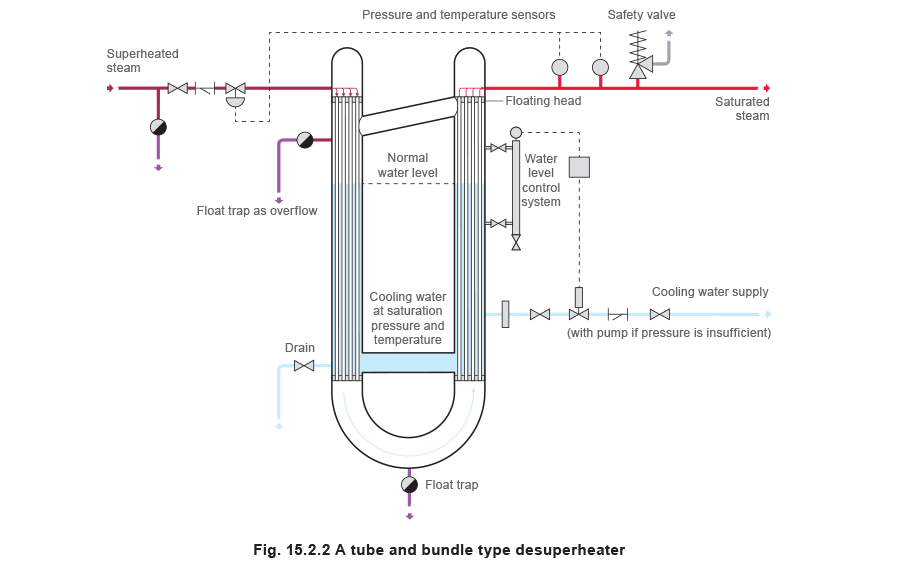
This type of desuperheater (Figure 15.2.2) consists of a heat exchanger, typically a shell and tube, with superheated steam on one side, and the cooling medium on the other.
The shell of the first heat exchanger (containing the cooling water) is fixed at both ends on the inlet side, whereas on the outlet side, it is fixed at the bottom and open at the top. The floating head allows the pressure in the two sections of the shell to equalise.
The cooling medium is water at saturation temperature and pressure. As superheated steam enters the first and then the second set of tubes, it gives up heat to the water, some of which will be evaporated by this addition of energy. Any evaporated cooling water passes through the floating head and will accumulate in the outlet side of the shell. It then passes through the open end of the shell where it is mixed with the desuperheated steam.
Advantages:
- Turndown is only limited by the controls that are fitted.
- This design is capable of producing desuperheated steam to within 5°C of the saturation temperature.
- High maximum operating temperatures and pressures, typically around 60 bar and 450°C.
- Fast response.
Disadvantages:
- Bulky - because there are now a number of in-line devices available, they have been largely superseded.
- Cost.
- An important concern with this type of desuperheater is the efficiency of the heat exchange process. The build up of air or scale films on the heat exchange surface can act as an extremely effective barrier to heat transfer.
Applications:
1. Those applications that experience wide variations in load.
Direct contact desuperheaters
Water bath type desuperheater
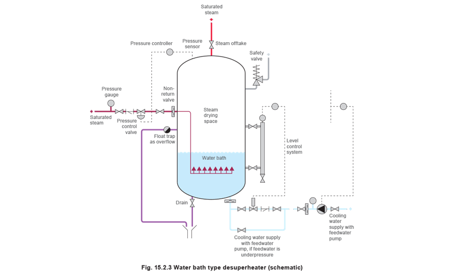
This is the simplest form of direct contact desuperheater. The superheated steam is injected into a bath of water. This additional heat will cause saturated steam to evaporate from the surface of the bath. A pressure controller maintains a constant pressure in the vessel, and hence the temperature and pressure of the saturated steam in the downstream pipe.
Since the superheated steam has more energy per unit mass than the saturated steam, more steam will be evaporated than actually enters the desuperheater. Consequently, the water level will fall and therefore provision must be made to maintain this level. This usually requires a pump of similar design to a boiler feedwater pump, as the water must be pumped against the vessel pressure.
A good non-return valve is required in the superheated steam supply to avoid any water from the bath being drawn into the superheated steam system should the pressure in the superheated main drop.
Advantages:
- Simple
- Steam is produced at saturation temperature.
- Steam with a dryness fraction of 0.98 can be produced.
- Turndown is only limited by the controls that are fitted.
Disadvantages:
- Bulky.
- Not practical for high temperatures.
Applications:
- Wide variations in the flowrate.
- Where no residual superheat can be tolerated.
Water spray desuperheating
This type of desuperheating represents the vast majority of desuperheating applications. In water spray desuperheaters, superheated steam is passed through a section of pipe fitted with one or more spray nozzles. These inject a fine spray of cooling water into the superheated steam, which causes the water to be converted into steam, reducing the quantity of superheat.
The cooling water may be introduced into the superheated steam in a number of ways; consequently, there are a number of different types of water spray desuperheater.
Despite this, most water spray desuperheaters are affected by the following factors:
- Particle size - The smaller the water particle size, the greater the ratio of surface area to mass, and the higher the rates of heat transfer. Since the water is being directly injected into the moving superheated steam, the smaller the particle size, the shorter the distance required for heat exchange to take place.
The water is broken into small particles using either a mechanical device (such as a variable or fixed orifice nozzle) or steam atomising nozzles.
- Turbulence - As the flow within the pipeline becomes more turbulent, the individual entrained water particles reside longer in the desuperheater, allowing for greater heat transfer. In addition, turbulence encourages the mixing of the cooling water and the superheated steam. Increased turbulence results in a shorter distance being required for complete desuperheating to occur.
Turbulence can be created in two ways:
- Pressure drop across the nozzle - Subjecting the cooling water to a higher pressure drop will increase its velocity and induce greater turbulence.
- Velocity - By increasing the overall velocity of the water and steam mixture, the amount of turbulence is inherently increased. The increase in velocity is usually achieved by creating a restriction in the steam path, which further generates turbulence by vortex shedding.
In addition to these high velocities, if poor piping design practices are used, the speed of the superheated steam could in theory approach Mach 1. At such speeds a number of problems would occur (including the generation of shock waves). However, this would be far in excess of the velocities used in good piping design. Typical velocities of steam entering a desuperheater should be around 40 to 60 m/s.
- Cooling water flowrate - The rate at which cooling water can be added to the superheated steam is affected by a number of factors, which are related by Equation 4.2.11:
Bearing in mind that C and g are constants, reviewing Equation 4.2.11 shows that only two factors can be manipulated to alter the cooling water flowrate, qv:
Changing the pressure drop over the orifice (nozzle), h - Expressing flowrate as a function of pressure drop over the nozzle:
This means that if, for example, flow is increased by a factor of 5, the available pressure must increase by a factor of 52 = 25. The effect of this relationship is to severely hamper the turndown ratio.
In addition to affecting the cooling water flowrate, there are two other important considerations when determining the required cooling water pressure:
- The cooling water pressure must be greater than the superheated steam pressure at the point of injection.
- The greater the pressure drop across the nozzle, the better the atomisation of the cooling water.
Changing the area of the orifice, A - Expressing flowrate as a function of the area of the orifice:
V ∝ A
This direct relationship means that if, for example, flow is to be increased by a factor of 5, the available area must also increase by a factor of 5. This change may simply be achieved by an orifice, which has the ability to change in area (see Figure 15.2.4), or alternatively by altering the number of orifices passing the coolant.
- Thermal sleeves - Careful control of the spray is required to ensure that the water does not fall out of suspension as this can result in thermal stresses being generated in the pipeline and cracking may occur. However, in some cases, an inner thermal sleeve can be used to provide protection from this.
The thermal sleeve also allows the circulation of superheated steam around the annular area between the sleeve and the inside diameter of the pipe. This provides a hot surface upon which the injected water can evaporate, as opposed to the walls of the desuperheater, which are inevitably cooler.
Water spray type desuperheaters
Single point radial injection spray desuperheaters
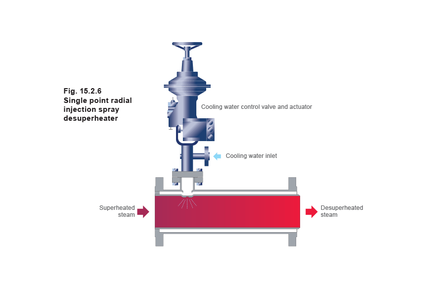
The simplest method of injecting cooling water is to introduce a nozzle through the pipe wall.
The cooling water particles are sprayed across the flow of the superheated steam. The quantity of cooling water injected is controlled by varying the position of the valve in the centre of the nozzle.
Advantages:
- Simple in operation.
- Cost effective.
- Minimum steam pressure drop.
Disadvantages:
- Low turndown ratio, typically a maximum of 3:1 on both steam and cooling water flow.
- Desuperheated steam temperature can only be reduced to 10°C above saturation temperature.
- Longer absorption length than the steam atomising type.
- Most prone to cause erosion damage to the internal pipework. This can be overcome by the use of a thermal sleeve.
- Limited pipe sizes.
Applications:
- Constant steam load.
- Constant steam temperature.
- Constant coolant temperature.
All of which mean a relatively constant cooling water requirement.
Multiple point radial injection spray desuperheaters
This is a progression of the single point radial injection spray desuperheater. Cooling water is sprayed in from a number of orifices around the perimeter of the pipe.
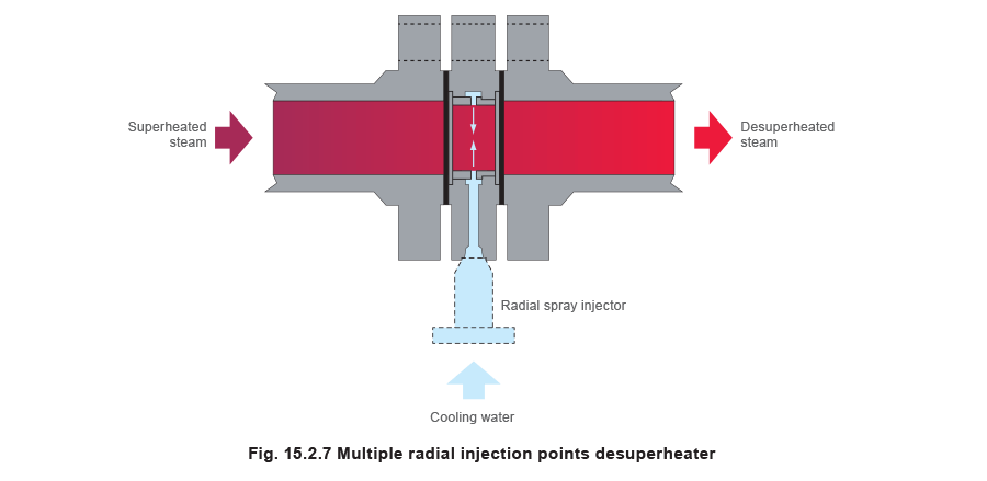
Advantages:
- The pressure of the cooling liquid is less than that in the single point version; therefore, it is not necessary to use a thermal sleeve.
- The absorption length is shorter compared with that of the single point version due to better mixing of the water and the superheated steam. The absorption length is still significantly longer than other types of water spray desuperheater.
Other advantages, disadvantages and applications are similar to those of single point radial injection spray desuperheaters.
Axial injection spray desuperheaters
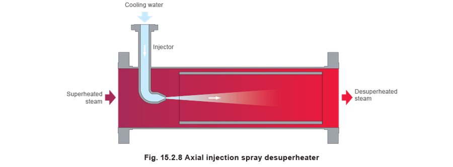
This is also a simple in-line injection spray desuperheater, but the point of injection is moved to the axis of the pipeline. The cooling water is injected into the steam flow via one or more atomising nozzles (see Figure 15.2.8). The unit usually employs a thermal sleeve.
Axial injection of the cooling water improves the mixing of the water and the superheated steam by two methods:
- As the water is injected along the centre of the pipeline, it will be more evenly distributed throughout the superheated steam.
- The cooling water delivery pipe that is inserted in the pipeline acts as an obstruction, creating additional turbulence at the point of water injection due to vortex shedding.
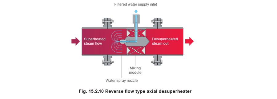
A modification of this basic arrangement involves turning the nozzle so that the cooling water is sprayed upstream, against the steam flow. The high velocity of the superheated steam reverses the spray water flow pattern and sends it back through a mixing chamber. This achieves more efficient mixing of the water and steam over a short absorption length.
Advantages:
- Simple in operation.
- No moving parts.
- Cost effective across the entire range of sizes.
- Minimal steam pressure drop.
Disadvantages:
- Low turndown ratio, typically a maximum of 3:1 on both steam and cooling water flow.
- Desuperheated steam temperature can only be reduced to 10°C above saturation temperature.
- Longer absorption length than the steam atomising type, but less than the radial type desuperheaters.
- Most prone to cause erosion damage to the internal pipework. This can be overcome by the use of a thermal sleeve.
Applications:
- Constant steam load.
- Constant steam temperature.
- Constant coolant temperature.
All of which mean a relatively constant cooling water requirement.
Multiple nozzle axial injection desuperheaters
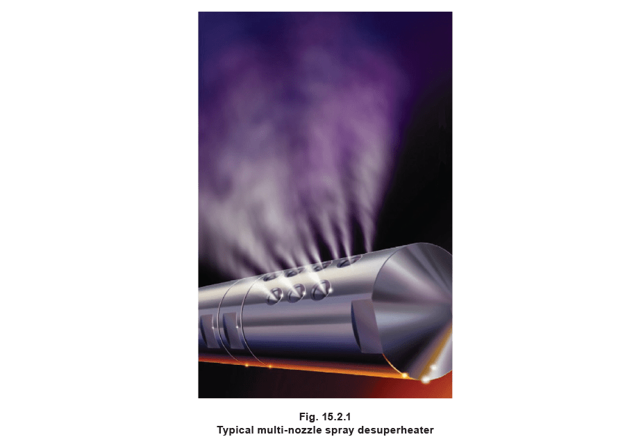
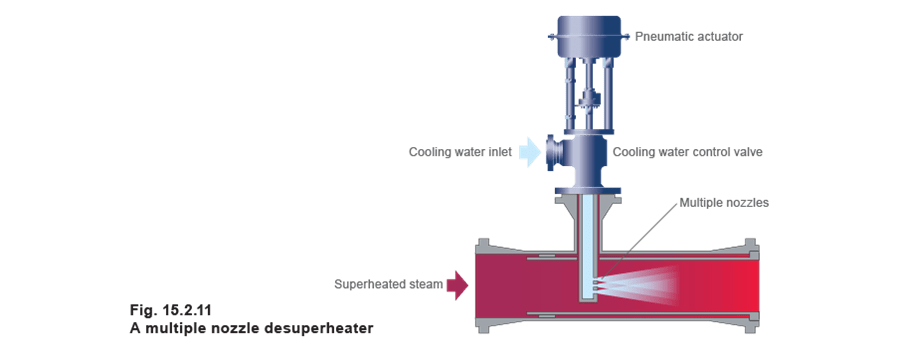
Rather than a single nozzle, the multiple nozzle axial injection desuperheater provides a number of nozzles across the flow of superheated steam. This gives good dispersion of the water droplets. There are three main types of multiple nozzle axial injection desuperheater:
1. Fixed area type - All the nozzles are open when the desuperheater is operating, and the cooling water is regulated by a spray water control valve.
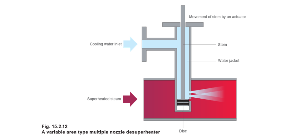
2. Variable spray type - The downstream temperature determines the number of exposed nozzles. Cooling water enters the desuperheater through the water jacket to the sealing area above the disc (see Figure 15.2.12). When an increase in the downstream steam temperature is detected by the associated temperature control system, the actuator moves the stem down, progressively exposing more nozzles. When the demand for the cooling water changes, the stem and disc arrangement moves up and down as required. This has the effect of changing the overall orifice area.
3. Spring-assisted type - This is essentially a combination of the two previous types. Instead of the stem and disc arrangement being controlled by an actuator, the spring-assisted type contains a spring-loaded flow plug, which moves in response to a change in the differential pressure between the coolant and the superheated steam. The moving plug changes the number of open nozzles, thereby adjusting the flow into the main pipeline. In addition, the cooling water is regulated by a spray water control valve.
Being able to control both the pressure and flow of the cooling water enables accurate control over the amount of water injected into the superheated steam. This type does, however, require a high cooling water pressure.
Advantages:
- Turndown ratios of up to 8:1 are possible with the fixed area type, up to 9:1 with the spring assisted type and 12:1 for the variable area type.
- Better dispersion of the water droplets means that the absorption length is less than that of single nozzle devices.
- Minimal steam pressure drop.
Disadvantages:
- The desuperheated steam temperature can only be reduced to 8°C above saturation temperature.
- Longer absorption length than the steam atomising type.
- Most prone to cause erosion damage to the internal pipework, if a thermal sleeve is not used.
- Not suitable for small pipe sizes.
- Requires high pressure cooling water (particularly true of the spring assisted type).
- Variable area and spring assisted types can be expensive.
Applications:
- Applications with a requirement for a higher turndown ratio than that offered by single nozzle devices, but where the expense of more sophisticated devices is not justified.
- Constant steam load.
- Constant steam temperature.
- Constant coolant temperature.
All of which require a relatively constant desuperheating load.

